
Flame manometer by Max Kohl
The manometric flame apparatus was developed by Rudolph Koenig in 1862, and was used

Illustration of two manometric traces, from ut3 and ut4 flames; the bottom trace has twice the frequency of the top. From Koenig’s Acoustic Catalogue, 1865.
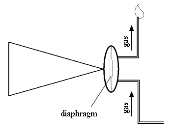
throughout the field of acoustics prior to the 20th-century advancement of more precise methods of examining the shape of sound waves, such as the phonodeik or modern oscilloscopes. In this device, a sound wave is captured by a cone, which connects to one
side of an enclosed capsule. The capsule is bisected by a rubber diaphragm. On the other side, flammable gas is flowing upward to supply the flame. The rubber diaphragm acts as a modulator for the gas flow, causing the height of the flame to change with the pressure variations in the sound.

Hand-cranked rotating mirror
The departmental collection of letters contains a letter from Rudolph Koenig to A. A. Michelson, 1883, explaining (in French) how to replace the rubber membrane inside the flame manometer.
Here are two video recordings of the flame manometer in action. The half-inch tall flame is viewed through the large rotating mirror, pictured below. One can see the flame rising and falling with the pressure changes on the diaphragm.